MQTT Integrated Doorbell
Hardware
I wanted a solution that wouldn’t require me to run any new wiring and w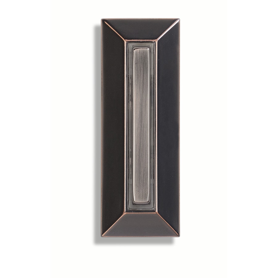 ould appear normal from the outside. I recently replaced my crappy builder-grade doorbell switch that had shattered from the plastic having heat cycled for 10 years with a much more attractive and sturdy button. I decided that I’d like to keep it so I did some digging to learn about how doorbells work. With a traditional doorbell there’s a transformer installed somewhere in the house that converts the wall voltage (110VAC in the US) to somewhere between 8 and 16VAC. The button on the outside of the house is wired in series between the power supply and a solenoid. There’s a “grain of wheat” bulb in the switch that illuminates the switch. It’s able to do this because it doesn’t draw enough current to trigger the solenoid to ring the bell. Pressing the button engages some flat metal springs that short the connection allowing enough current to flow so that the solenoid engages and pushes the hammer into the tone arm.
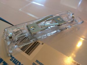 In this picture you can see the flat metal springs that live inside the doorbell housing. I’ve removed this from inside the button housing; the button normally sits on top of these springs. On the lower part of the spring you can see the solder points where the small wires that connect the light bulb. We want to do essentially the same thing but with DC so our microcontroller can handle the signal. First you’ll need to figure out what voltage allows your LED to illuminate to the desired level and what size resistor you’ll need to protect the LED.
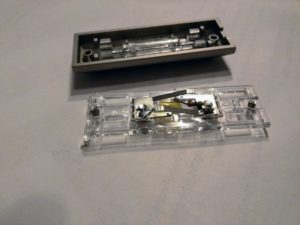 In this photo you can see the modifications I’ve made to the button to allow it to use DC components. There’s a LED and a resistor installed in-place of the grain of wheat bulb. This acts in a similar manner as it will allow voltage to flow to illuminate the LED but we need to then lower the voltage so as not to trigger the microcontroller to register a HIGH state unless the button is actually being pressed. To do this we’ll use a voltage divider circuit. First we’ll need to figure out the microcontroller’s input voltage. Install a potentiometer with the wiper going to a digital input pin and write up a quick sketch to output the state of the pin on the serial monitor.
const int POT_PIN = D1;
void setup() {
Serial.begin(1152000);
pinMode(POT_PIN, INPUT);
}
void loop() {
int pinVal = digitalRead(POT_PIN);
if (pinVal == HIGH) {
Serial.println("Pin is high");
} else {
Serial.println("Pin is low");
}
delay(1000);
}[/code]
After you’ve figured out your trigger voltage you need to measure the voltage drop across your LED. Enter the source voltage (V1) into the Sparkfun calculator and adjust the resistor values until the output voltage (V2) is slightly less than or equal to your trigger voltage. With the sketch running and your voltage divider in place open the serial monitor and make sure that pressing the button registers a HIGH on the microcontroller.
If the voltage difference is minimal, you may be able to get away with putting a pulldown resistor on the input pin to avoid the voltage divider circuit. The NodeMCU I was using uses 3.3V logic so I was able to use this approach.
My circuit ended up looking like this.
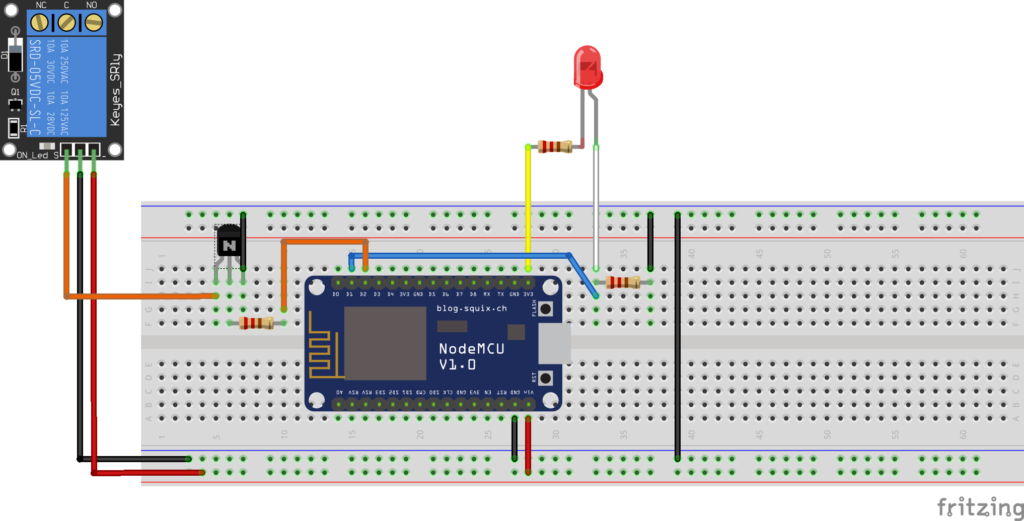
One leg of the transformer’s output goes directly to the solenoid and the other goes through this relay. The NodeMCU will actually control the relay in order to ring the doorbell. On the flip side, it can also be told to *not* ring the doorbell.
Hardware Used
- Wemos D1 Mini
- Wemos relay module
- Wemos protoshield
- Buck converter
- Components from
MQTT Sensor Node